


 English
 中文简体
中文简体 русский
TD Inline Circulation Pump: Design, Performance & Installation
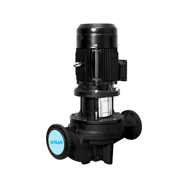
The TD inline circulation pump is a single-stage, close-coupled centrifugal pump designed specifically for direct integration into pipework, with the suction and discharge ports aligned on a common axis. This inline configuration is its defining structural characteristic: the pump fits directly into the pipeline without the need for a baseplate, a flexible coupling, or the complex alignment procedures that a base-mounted pump requires. The key performance insight is that a TD pump is optimized for medium to high flow rates at low to moderate head, making it the default choice for closed-loop heating and cooling circuits, domestic hot water recirculation, solar thermal systems, and industrial heat transfer applications. The pump's hydraulic section, typically constructed from cast iron, bronze, or stainless steel depending on the fluid, is matched to a close-coupled motor that is cooled by the pumped fluid itself, eliminating the need for a separate cooling fan and enabling the characteristic low-noise operation that makes these pumps suitable for installation in occupied spaces.
Content
- 1 The Inline Advantage: Why Axial Port Alignment Matters
- 2 Hydraulic Design and Impeller Types
- 3 Motor Technology and Speed Control
- 4 Mechanical Seal: The Primary Wear Component
- 5 Pipework Integration and Installation Requirements
- 6 NPSH, Cavitation, and System Pressure Requirements
- 7 Selection Parameters and Performance Curves
- 8 Commissioning, Air Venting, and First Start-Up
- 9 Troubleshooting Common TD Pump Failures
The Inline Advantage: Why Axial Port Alignment Matters
In a conventional end-suction pump, the fluid enters the impeller eye axially and discharges radially, requiring a 90-degree turn in the flow path and a volute casing to convert velocity to pressure. A TD inline pump abandons the volute in favor of a concentric casing design with an annular discharge passage that collects flow from the impeller periphery and redirects it back to the pump axis. The suction and discharge flanges are the same nominal diameter and share the same centerline, which means the pump can be installed by simply bolting it between two pipe flanges. The pipework supports the pump; no separate foundation is required. This installation simplicity translates directly to lower installed cost: no grouting, no laser alignment, no flexible connectors needed for vibration isolation beyond what the pipe hangers provide.
The concentric casing also provides a self-venting feature. Because the discharge passage surrounds the impeller axisymmetrically, any entrained air is naturally swept out of the casing with the liquid flow rather than accumulating at the top of a volute and causing the classic "air-bound" pump failure. This makes the TD design particularly well-suited to systems where air separation is a challenge, such as the top floors of high-rise buildings or systems with intermittent operation.
Hydraulic Design and Impeller Types
The TD pump's impeller is a closed, single-suction design, with curved vanes sandwiched between a front and rear shroud. The impeller is directly mounted onto the extended motor shaft, which is the "close-coupled" aspect of the design—there is no separate pump shaft, no bearing housing on the pump side, and no coupling to align. The motor bearings carry both the motor rotor and the pump impeller as a single rotating assembly. This design simplicity reduces the number of wear components to essentially two items: the mechanical shaft seal and the motor bearings.
The impeller diameter is trimmed to match the duty point on the pump's performance curve. A given TD pump model family may offer multiple impeller diameters, each shifting the performance curve vertically without changing the casing size. The operating point is selected by intersecting the system curve—the head required to overcome friction and static lift at a given flow rate—with the pump curve. The ideal selection places the duty point within the middle 50% of the pump's flow range, near the Best Efficiency Point (BEP). Operating too far to the left of the BEP subjects the impeller to radial thrust that accelerates bearing and seal wear. Operating too far to the right risks cavitation as the Net Positive Suction Head Available (NPSHa) in the system falls below the pump's NPSH required (NPSHr).
Motor Technology and Speed Control
Modern TD inline pumps are increasingly equipped with permanent magnet synchronous motors (PMSM) driven by integrated variable frequency drives (VFDs), replacing the traditional single-speed or three-speed induction motor. The shift from fixed-speed to variable-speed operation is the single most significant efficiency improvement in circulation pump technology. In a heating system, the pump operates at full design flow for only a small fraction of the heating season—typically less than 5% of the operating hours. For the remaining 95% of the time, the system is at part load, and a fixed-speed pump would waste energy by pumping at full flow against partially closed control valves. A variable-speed pump with differential pressure control ramps down to match the actual system demand, following the pump affinity laws: a 20% reduction in speed yields approximately 50% reduction in power consumption.
The integrated VFD offers multiple control modes, selectable via a user interface on the motor terminal box or through a building management system (BMS) connection. The most common modes for TD pumps in HVAC applications are:
- Constant pressure control: The pump maintains a fixed differential pressure setpoint regardless of flow. Ideal for systems with two-way control valves where the pressure at the most remote terminal must be maintained.
- Proportional pressure control: The differential pressure setpoint varies linearly with flow, reducing from the design setpoint at full flow to a minimum setpoint (typically 50% of design) at zero flow. This mimics the natural quadratic system curve and provides additional energy savings in distribution systems with linear piping losses.
- Constant speed control: The pump runs at a fixed user-set speed. Used for open-loop applications like condenser water where flow must be maintained for heat rejection regardless of pressure.
- Temperature control: The pump speed is modulated to maintain a set temperature differential across the supply and return, ensuring the flow rate matches the actual heat transfer demand.
Mechanical Seal: The Primary Wear Component
The mechanical shaft seal is the barrier between the pumped fluid and the motor bearings and windings. In a TD inline pump, the seal is positioned on the motor shaft directly behind the impeller, running against a stationary seat pressed into the pump casing. The standard seal for HVAC water applications is a carbon vs. ceramic face combination with an EPDM (ethylene propylene diene monomer) elastomer secondary seal. This material combination is compatible with water, water-glycol mixtures up to 50% concentration, and typical HVAC corrosion inhibitors. The seal faces operate with a thin fluid film between them—typically less than 1 micron thick—that simultaneously lubricates and cools the interface. A visible leak of a few drops per minute during initial run-in is normal and will subside as the faces lap themselves together. A persistent drip after 24 hours of operation indicates a damaged seal face, an incorrectly installed seal, or an abrasive contaminant embedded in the seal interface.
For high-temperature applications above 120°C, such as pressurized hot water or thermal oil systems, the standard carbon-ceramic seal is upgraded to a silicon carbide vs. silicon carbide face combination with a Viton (FKM) or PTFE bellows. Silicon carbide has a higher thermal conductivity than ceramic and can dissipate the frictional heat more effectively, preventing the localized face temperature from exceeding the fluid's boiling point and causing the seal to run dry. The seal flushing arrangement, which circulates a small portion of the pump discharge flow across the seal faces, must be verified as functional before commissioning any TD pump in high-temperature service.
Pipework Integration and Installation Requirements
The inline design simplifies installation but also imposes specific constraints that, if ignored, reduce pump life and hydraulic performance. The primary installation rule is that the pump must never be used as a pipe support. The pump casing is designed to withstand the system pressure, not the weight and bending moments of connected pipework. The pipes on both suction and discharge sides must be independently supported by hangers or supports within 50 cm of the pump flanges. The pipe flanges must be parallel and aligned to within 1 mm before the bolts are tightened. Forcing the flanges together with the bolts to close a gap introduces a bending moment on the pump casing that distorts the seal seat and causes premature seal failure.
A minimum of five pipe diameters of straight, unobstructed pipe must be provided on the suction side of the pump. This allows the flow profile to develop into a uniform, axisymmetric distribution before entering the impeller eye. Installing an elbow, a tee, or a valve immediately adjacent to the suction flange creates an asymmetric velocity profile that causes unbalanced loading on the impeller, increased vibration, and a reduction in the available NPSH. For TD pumps installed in tight mechanical rooms where space constraints prevent a full five-diameter straight run, a flow straightener or a suction diffuser can be used to condition the flow, but this increases the suction-side pressure drop and must be accounted for in the NPSH calculation.
NPSH, Cavitation, and System Pressure Requirements
Cavitation is the formation and violent collapse of vapor bubbles in the low-pressure region at the impeller eye, and it is the fastest way to destroy a pump impeller. The damage is unmistakable: a pitted, spongy-looking impeller surface that appears to have been attacked with a ball-peen hammer. Preventing cavitation requires that the NPSH available in the system exceeds the pump's NPSH required at the operating flow by a safety margin of at least 0.5 to 1.0 meter. NPSH available depends on the static pressure at the pump suction, which is determined by the system fill pressure, the elevation of the pump relative to the system's highest point, and the suction-side friction losses.
In a closed-loop hydronic system, the fill pressure is set by the expansion tank pre-charge pressure. A typical multi-story building requires a fill pressure at the lowest point—which is often where the TD pump is located—sufficient to maintain a positive pressure of at least 0.5 bar (7 psi) at the top of the system plus the static height of the water column. If the pump is in the basement of a 30-meter tall building, the static pressure at the pump is approximately 3 bar from the water column alone, plus the 0.5 bar positive pressure, giving a suction pressure of 3.5 bar. This is well above the NPSH requirement of any standard TD pump for water service. Cavitation becomes a risk in systems with low fill pressure, high suction-side friction losses, or when the pump is operating at a flow far to the right of its BEP where the NPSHr increases sharply.
Selection Parameters and Performance Curves
Selecting a TD inline pump requires matching three system parameters to the pump's performance curve: the design flow rate, the total dynamic head, and the required NPSH. The table below provides a representative mapping of common TD pump sizes to their hydraulic coverage, based on typical 4-pole (1450 rpm) motor speed for 50 Hz power supply.
| Pump Size (DN Suction/Discharge) | Flow Range at BEP | Max Head (Single Stage) | Typical Motor Power Range | Common Application |
|---|---|---|---|---|
| TD 32 (DN 32 / 1¼") | 2-8 m³/h | 10-15 m | 0.37-0.75 kW | Small heating zones, DHW recirculation |
| TD 50 (DN 50 / 2") | 8-25 m³/h | 12-20 m | 1.1-2.2 kW | Medium building heating circuits, condenser water |
| TD 65 (DN 65 / 2½") | 25-60 m³/h | 15-25 m | 3.0-5.5 kW | Large building primary loops, district heating |
| TD 80 (DN 80 / 3") | 40-100 m³/h | 18-28 m | 5.5-11.0 kW | Industrial process cooling, large boiler feed |
| TD 100 (DN 100 / 4") | 60-160 m³/h | 20-32 m | 7.5-15.0 kW | District cooling, plant-wide circulation loops |
The pump size designation typically refers to the nominal bore of the suction and discharge flanges in millimeters, which corresponds to the pipe diameter the pump is designed to match. A TD 50 is intended for a 50 mm (DN 50) pipe system. Undersizing the pump relative to the pipework introduces a velocity head loss at the sudden enlargement that reduces the pump's effective head. Oversizing the pump relative to the pipework forces the use of reducing flanges and may push the operating point to an inefficient region of the pump curve.
Commissioning, Air Venting, and First Start-Up
A dry start—energizing the motor with the pump casing full of air—will destroy the mechanical seal within seconds. The fluid film that lubricates and cools the seal faces is absent in air, and the faces overheat and fracture. Before the motor is energized for the first time, the pump and the surrounding pipework must be fully vented and filled. The fill point should be on the suction side of the pump, and the air vent plug on the top of the pump casing must be opened until a steady stream of water, free of air bubbles, flows out. For pumps installed at high points in the system where air naturally collects, automatic air vents should be installed in the adjacent pipework.
The direction of rotation must be verified before the pump is operated under load. A three-phase motor connected with reversed phase rotation will spin the impeller backward, producing flow in the correct direction but at drastically reduced head and flow. Bump the motor momentarily—less than one second—and observe the rotation direction through the motor's fan cover or by the shaft movement at the coupling. The correct rotation direction is indicated by an arrow on the pump casing. After confirming rotation, start the pump with the discharge valve partially open and gradually open it to the design operating point while monitoring the motor current draw against the nameplate full-load amperage.
Troubleshooting Common TD Pump Failures
The most frequent operational issues with TD inline pumps and their root causes are well-defined. Systematic diagnosis avoids unnecessary component replacement.
- Pump runs but delivers no flow: The most common cause is air binding—the pump casing is not fully vented. Second possibility is a closed isolation valve upstream or downstream. Third possibility is a severely worn impeller, particularly if the system water has been poorly treated and contains abrasive particles that have eroded the impeller vanes over time.
- Noisy operation with cavitation sounds (gravel in the pump): Insufficient suction pressure. Check the system fill pressure at the expansion tank, verify that the suction strainer (if fitted) is not clogged, and confirm that the pump is not operating at a flow rate far to the right of its curve where NPSHr rises sharply.
- Persistent leak from the mechanical seal area: If the leak does not stop after 24 hours of run-in, the seal faces are damaged, misaligned, or contaminated. Replace the mechanical seal cartridge and verify that the shaft surface under the seal is free of scoring. A worn motor bearing that allows radial shaft movement will also cause a seal leak that cannot be fixed by replacing the seal alone.
- Motor overloads and trips on overcurrent: The pump is operating at a flow far to the right of its BEP, drawing more power than the motor is rated for. The solution is not a larger motor, which would overload the pump shaft, but throttling the discharge valve to bring the operating point back onto the allowable portion of the pump curve, or, for a variable-speed pump, reducing the speed setpoint.
- Excessive vibration transmitted to pipework: Check for pipe strain from misaligned flanges, which distorts the pump casing. Verify that the pipe supports are independent of the pump and that the suction piping has the required straight run length. If vibration persists, a worn or unbalanced impeller is the likely cause.

Recommended Products
It is focused on the overall solution of dry bulk material port transfer system,
research and development, manufacturing, and service


 English
-
 Factory Area 5-6, No. 1118 Xin'an Road, Nanxun Town, Huzhou City, Zhejiang Province
-
 +86-4008117388
-
 [email protected]
Copyright © Zhejiang Zehao Pump Industry Co., Ltd. All Rights Reserved. Stainless Steel Multistage Centrifugal Pumps Manufacturers

