

 English
 中文简体
中文简体 русский
Types of Centrifugal Pumps: Self-Priming, Multistage & vs PD
Centrifugal pumps are the most widely used pump type in the world, covering the majority of water, process, and HVAC applications — but the category contains many distinct types: end-suction, inline, split-case, self-priming, multistage, submersible, and vertical turbine, each suited to a specific range of flow, head, and installation conditions. The fundamental difference between a centrifugal pump and a positive displacement pump is that centrifugal pumps generate pressure by accelerating fluid through a rotating impeller, while positive displacement pumps move fixed volumes per revolution regardless of system pressure. For high flow at moderate head, centrifugal pumps are almost always the right choice; for high pressure at low flow, or for viscous fluids, positive displacement pumps win. This article covers all major centrifugal pump types, self-priming operation, multistage design, and the centrifugal vs. positive displacement decision in engineering-level detail.
Content
- 1 How Centrifugal Pumps Work: The Operating Principle
- 2 Types of Centrifugal Pumps: A Complete Classification
- 3 Self-Priming Centrifugal Pumps: How They Work and When to Use Them
- 4 Multistage Centrifugal Pumps: Achieving High Pressure
- 5 Difference Between Positive Displacement Pump and Centrifugal Pump
- 6 Selecting the Right Centrifugal Pump Type: A Decision Framework
How Centrifugal Pumps Work: The Operating Principle
All centrifugal pumps share the same fundamental operating principle: a rotating impeller imparts kinetic energy to the fluid, which is then converted to pressure energy in the volute or diffuser casing. The impeller draws fluid in axially at its eye (center), accelerates it radially outward through the vane passages, and discharges it tangentially into the volute. The volute's progressively expanding cross-section decelerates the high-velocity fluid, converting kinetic energy to static pressure — this conversion is described by Bernoulli's principle.
The head (pressure) generated by a centrifugal pump follows the Affinity Laws. Most critically: head is proportional to the square of impeller tip speed (H ∝ N²), flow is proportional to speed (Q ∝ N), and power is proportional to the cube of speed (P ∝ N³). Doubling pump speed quadruples head and increases power eight-fold — which is why variable speed drives (VSDs) offer dramatic energy savings when pump duty varies. Reducing speed by 20% cuts power consumption by approximately 50%.
Specific Speed: The Parameter That Defines Impeller Type
Specific speed (Ns) is a dimensionless parameter that characterizes the shape and performance of an impeller design at its best efficiency point. It determines whether a radial, mixed-flow, or axial impeller is most efficient for a given duty:
- Low specific speed (Ns 400–1,500): Radial flow impellers — narrow, closed vane design; high head, low flow. Used in multistage boiler feed pumps, high-pressure process pumps, and water supply systems.
- Medium specific speed (Ns 1,500–5,000): Mixed flow impellers — vanes discharge at an angle between radial and axial; moderate head and flow. Common in irrigation, water supply, and general industrial pumps.
- High specific speed (Ns 5,000–15,000): Axial flow (propeller) impellers — high flow, very low head. Used in flood control, drainage, and large irrigation lift stations.
Understanding specific speed prevents a common selection error: choosing a pump that operates far from its best efficiency point (BEP), which increases energy consumption, accelerates wear, and causes vibration. A pump operating at less than 70% or more than 120% of its BEP flow is operating in a zone of reduced efficiency and increased mechanical stress.
Types of Centrifugal Pumps: A Complete Classification
Centrifugal pumps are classified by several criteria simultaneously: casing configuration, impeller type, shaft orientation, number of stages, and installation arrangement. The most practically useful classification for selection purposes is by casing and installation type.
End-Suction Single-Stage Pump
The end-suction pump is the most widely produced centrifugal pump type globally. The suction nozzle faces axially toward the impeller eye; the discharge nozzle exits radially from the volute casing. The impeller is mounted on the shaft overhang (cantilever). This configuration provides:
- Simple, low-cost construction with easy access to the wet end for maintenance
- Compact footprint relative to flow capacity
- Availability in close-coupled (motor bolts directly to pump) and frame-mounted (separate bearing housing on baseplate) configurations
- Typical duty range: 1–5,000 m³/h flow, 5–200 m head
Standardized to ISO 2858 / ISO 5199 (process) and EN 733 (building services) dimensional standards, meaning pumps from different manufacturers are interchangeable. The dominant pump for HVAC, water supply, irrigation, and general process duties.
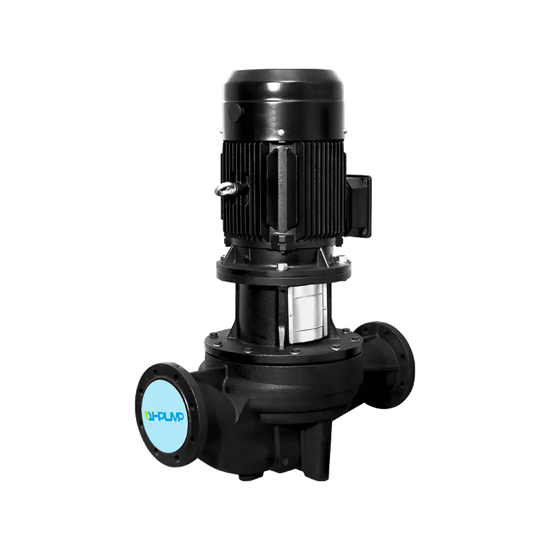
Inline (In-Line) Pump
The inline pump mounts directly in the pipeline — suction and discharge nozzles are in-line on the same centerline, so the pump is supported by the pipe without a separate baseplate. The motor is mounted vertically above the casing. Inline pumps offer significant installation advantages in building services — no separate pump room or baseplate is required, pipe runs are uninterrupted, and installation labor is minimal. Available in close-coupled and long-coupled (separate motor with coupling) variants. Typical duty: 1–500 m³/h, 5–80 m head. Widely used in HVAC circulation, water supply booster systems, and light process duties.
Split-Case (Double-Suction) Pump
In a split-case pump, the casing splits along a plane through the shaft centerline, allowing the complete rotating assembly (shaft, impeller, bearings) to be removed without disturbing the suction and discharge pipework. The impeller is typically double-suction — fluid enters both sides of the impeller simultaneously — which cancels axial thrust and allows very high flow rates with excellent efficiency. Split-case pumps are the standard choice for large water supply, irrigation, fire fighting, and municipal systems where flows of 500–10,000+ m³/h are required at heads of 20–150 m. The horizontal split-case configuration provides excellent field maintainability.
Vertical Turbine Pump (Deep Well Pump)
Vertical turbine pumps (VTPs) have their impeller(s) submerged at the bottom of a column pipe, with the motor mounted above ground at the top. They are the standard solution for deep well water extraction, cooling tower sump pumping, and large sump drainage. The column pipe transmits both liquid and mechanical shaft rotation between the submerged pump bowl and the surface motor. VTPs eliminate suction lift limitations entirely — the impeller is always flooded regardless of water table depth. Multiple bowl stages can be stacked to generate high heads. Typical applications: municipal wells (depths of 30–300+ m), agricultural irrigation, industrial cooling water intakes.
Submersible Pump
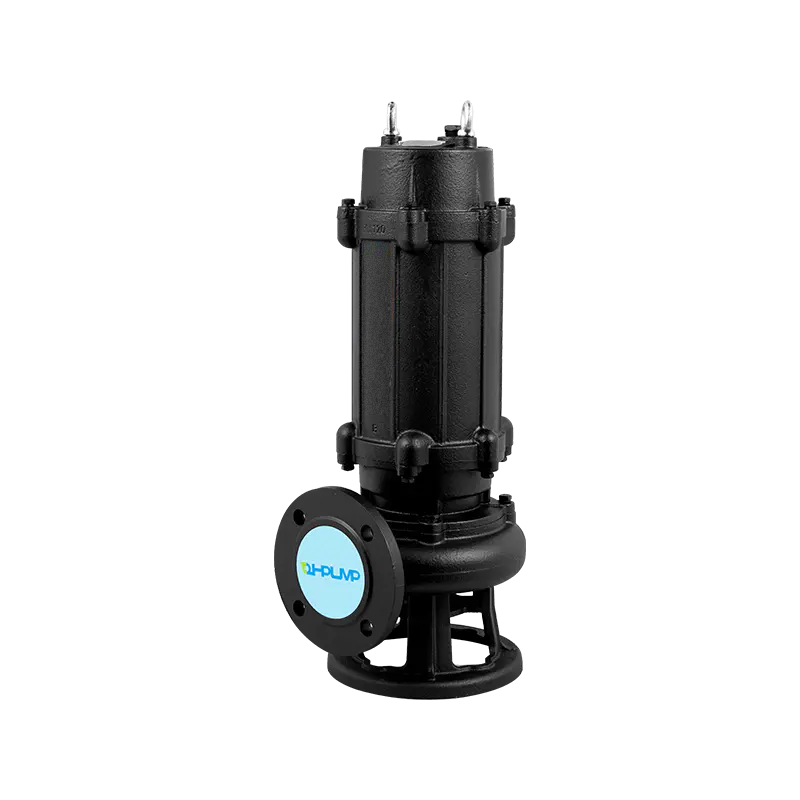
The submersible pump combines motor and pump in a sealed, waterproof unit that operates entirely submerged in the fluid being pumped. Motor cooling is provided by the pumped fluid flowing over the motor housing. Eliminating suction lift entirely and avoiding prime loss are the key operational advantages. Used in domestic and municipal wells, wastewater lift stations, stormwater drainage, and dewatering. The sealed motor requires careful motor protection — dry-running detection, moisture ingress sensors, and thermal overload protection are critical to reliable submersible pump operation.
Axial Flow and Mixed Flow Pumps
Axial flow pumps (propeller pumps) generate head primarily by the lift action of the impeller vanes acting on the fluid, similar to a ship's propeller. They are designed for very high flow rates (10,000–500,000+ m³/h) at very low heads (1–10 m) — drainage of floodplains, irrigation lift, cooling water for power stations, and wastewater treatment. Mixed flow pumps occupy the mid-range between radial and axial, handling high flows at moderate heads efficiently.
Centrifugal Pump Types: Performance Range Summary
| Pump Type | Flow Range (m³/h) | Head Range (m) | Impeller Type | Key Advantage | Primary Application |
|---|---|---|---|---|---|
| End-suction single-stage | 1–5,000 | 5–200 | Radial, closed | Low cost, compact | HVAC, water supply, general process |
| Inline | 1–500 | 5–80 | Radial, closed | No baseplate; easy install | Building services, HVAC circulation |
| Split-case (double-suction) | 100–10,000+ | 20–150 | Radial, double-suction | High flow; no thrust; maintainable | Municipal water, irrigation, fire |
| Vertical turbine | 10–5,000 | 20–600 | Radial or mixed, multi-stage bowls | Deep well; always flooded | Wells, cooling intakes, sumps |
| Submersible | 0.1–2,000 | 5–400 | Radial or mixed | No prime loss; self-cooling | Wells, wastewater, dewatering |
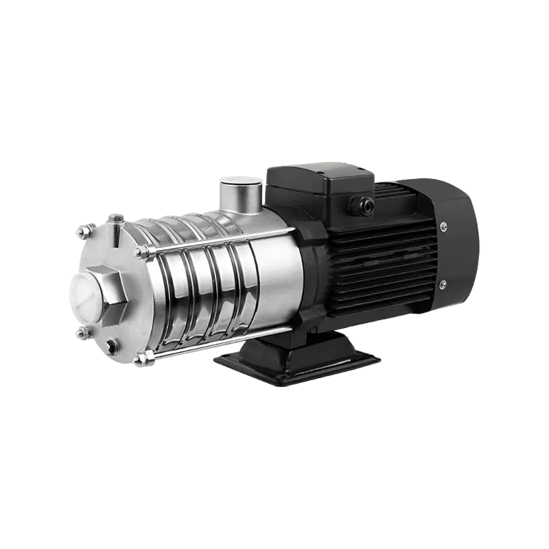
| Multistage horizontal | 1–500 | 50–1,000+ | Multiple radial stages | High pressure at moderate flow | Boiler feed, RO, pressure boosting |
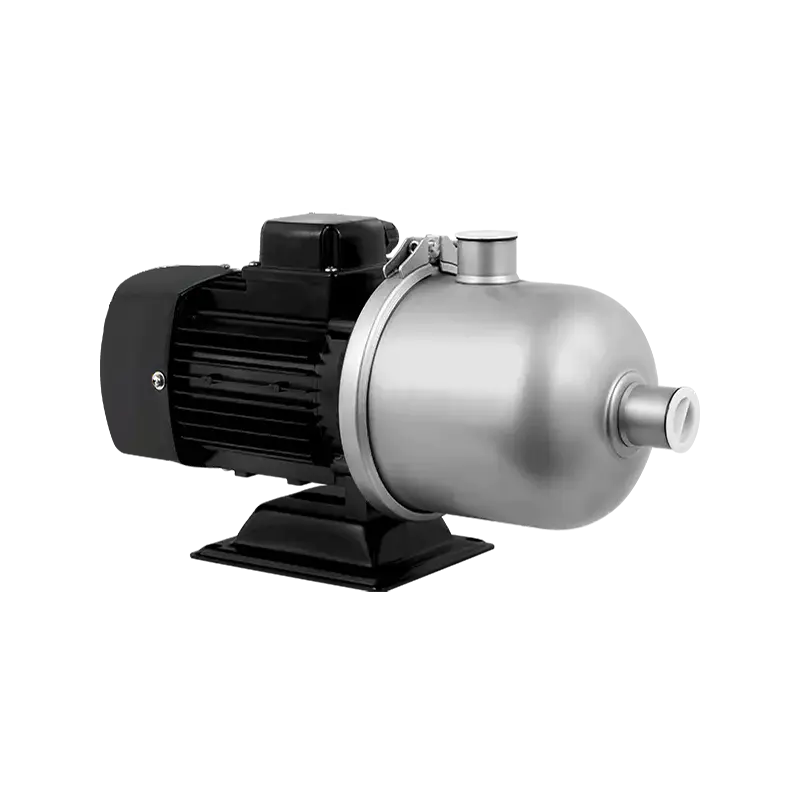
| Self-priming centrifugal | 1–1,000 | 5–80 | Radial, open or semi-open | Handles air; no priming needed | Dewatering, tanker unloading, mobile plant |
| Axial flow (propeller) | 500–500,000+ | 1–10 | Axial, open propeller | Extreme flow at minimal head | Flood drainage, cooling water, irrigation lift |
Self-Priming Centrifugal Pumps: How They Work and When to Use Them
A standard centrifugal pump cannot handle air — its impeller is designed to work with incompressible liquid, and if air enters the casing, the impeller spins without generating useful pressure, a condition called air-binding or loss of prime. A self-priming centrifugal pump incorporates a design that allows it to evacuate air from the suction line and prime itself without external assistance, enabling operation where the pump is installed above the liquid level.
The Self-Priming Mechanism
Self-priming centrifugal pumps use a large-volume recirculation chamber (volute reservoir) above the impeller that retains a charge of liquid when the pump stops. On restart, the impeller rotates in this retained liquid, creating a low-pressure zone at the impeller eye. Air from the suction line is drawn into the impeller and mixed with the recirculating liquid. The air-liquid mixture is discharged into the separator chamber, where centrifugal action and gravity separate the air (which vents to atmosphere through the discharge valve) from the liquid (which returns to the impeller inlet for another mixing cycle).
This recirculation process continues until all air has been purged from the suction line and liquid fills the pump — at which point normal pumping operation begins. The priming time depends on suction lift and pipe volume: typically 30 seconds to 3 minutes for suction lifts of 3–7 m. Maximum self-priming suction lift for most designs is 7–8 m — theoretical limit is approximately 10.3 m (one atmosphere) but in practice, friction losses, temperature, and imperfect sealing reduce this to 7–8 m for reliable operation.
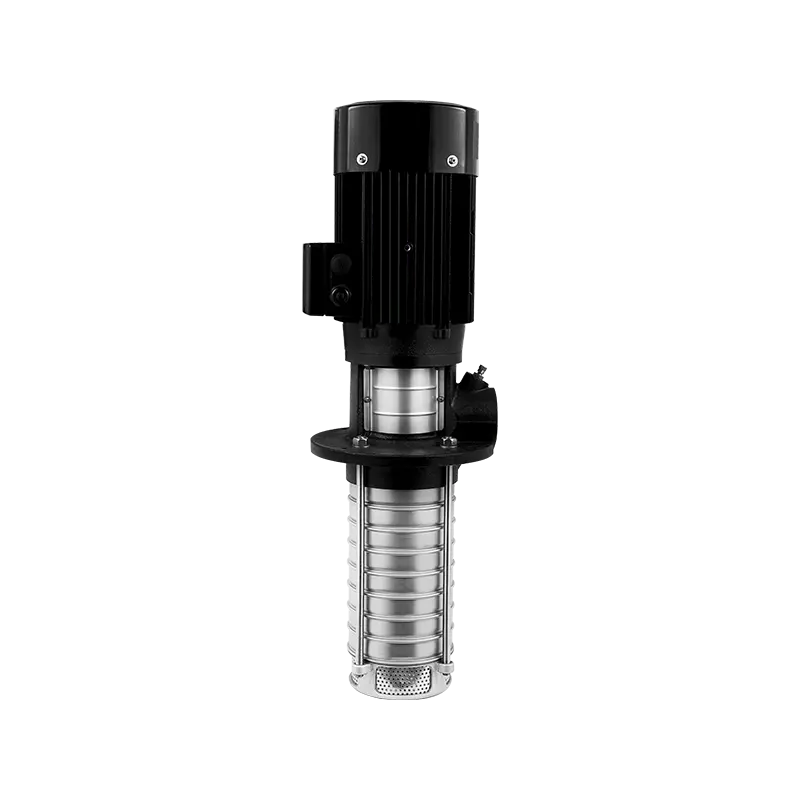
Types of Self-Priming Centrifugal Pump Designs
- Recirculation (side-channel) type: The most common design. The volute reservoir and side channel create the recirculation path described above. Simple construction, reliable priming, widely available. The standard general-purpose self-priming pump for dewatering, agricultural, and portable applications.
- Peripheral (regenerative) type: Uses a turbine-style impeller with many small vanes running in a close-clearance annular channel. The repeated regenerative action builds pressure in small increments per revolution, allowing high heads at low flows and excellent self-priming capability. Best for low-flow, high-head duties requiring self-priming — boiler feed in small installations, chemical dosing systems.
- Liquid ring pump (vacuum-assisted priming): Not a pure centrifugal pump, but a hybrid: a liquid ring pump assists priming of a conventional centrifugal stage. Used in large self-priming pump sets where the suction lift or line volume exceeds what a single recirculating centrifugal can handle — fire fighting pumps, large dewatering skids, tanker loading systems.
Applications Where Self-Priming Is Essential
- Dewatering and site drainage: Construction sites, mines, and excavations where the pump must be positioned above the pit or sump being emptied, and the liquid level falls below the pump as dewatering progresses
- Mobile and trailer-mounted pump sets: Agricultural irrigation from rivers and channels, tanker truck loading and unloading, emergency response pumping — all require a pump that primes automatically without manual foot valve filling
- Sewage and wastewater: Self-priming sewage pumps handle solids and entrained air from wet wells with variable and unpredictable liquid levels; the ability to handle intermittent air ingestion prevents the prime loss that would shut down a standard centrifugal
- Chemical and process applications with intermittent suction conditions: Where vapor pockets, gas release, or process interruptions can introduce air into the suction line — a self-priming pump restarts without manual intervention
Self-Priming vs. Standard Centrifugal: Key Trade-offs
Self-priming pumps sacrifice some hydraulic efficiency compared to equivalent standard centrifugal designs because the recirculation chamber adds turbulence and the impeller-to-casing clearances must be wider to allow air-liquid mixing. Typical self-priming pump efficiency is 5–15% lower than an equivalent standard centrifugal at the same duty point. For continuous-duty applications where the pump is always flooded, a standard centrifugal with a foot valve is more energy-efficient. Self-priming is justified when the installation genuinely cannot guarantee a flooded suction, or when unattended automatic restart capability is required.
Multistage Centrifugal Pumps: Achieving High Pressure
A single-stage centrifugal pump generates pressure proportional to the square of its impeller tip speed. To achieve very high heads without running a single impeller at destructive speed, multiple impeller stages are arranged in series — the discharge from each stage feeds directly into the suction of the next. Each stage adds an increment of head equal to the single-stage performance; ten stages produce ten times the head of one stage at the same flow and speed. This is the operating principle of all multistage centrifugal pumps.
Horizontal Multistage Pump Configuration
In a horizontal multistage pump, all impellers are mounted on a single shaft within a barrel or segmental casing. Between-stage diffusers or return channels guide flow from the discharge of one impeller to the suction of the next. Key design considerations:
- Axial thrust: Each impeller generates axial thrust in the direction of flow. In most multistage designs, impellers are arranged with opposing orientations (back-to-back staging) so that thrust from each half of the pump cancels, eliminating the large axial bearing loads that would otherwise occur.
- Interstage pressure: Casing and shaft seals must withstand progressively increasing pressures at each stage. The barrel casing design of high-pressure boiler feed pumps contains the full discharge pressure in the outer barrel — interstage seals only see differential pressure between adjacent stages.
- Stage count: Standard horizontal multistage pumps are available in 2–12 stages. High-pressure barrel pumps for boiler feed and reverse osmosis service can have 20+ stages, generating pressures exceeding 200 bar (20 MPa) in specialized designs.
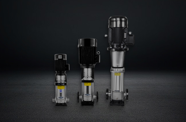
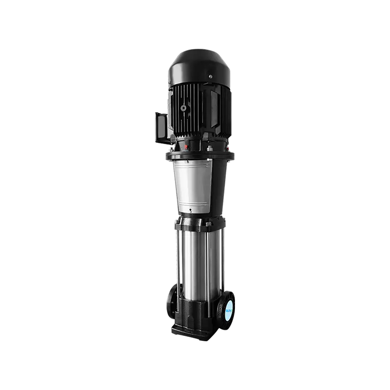
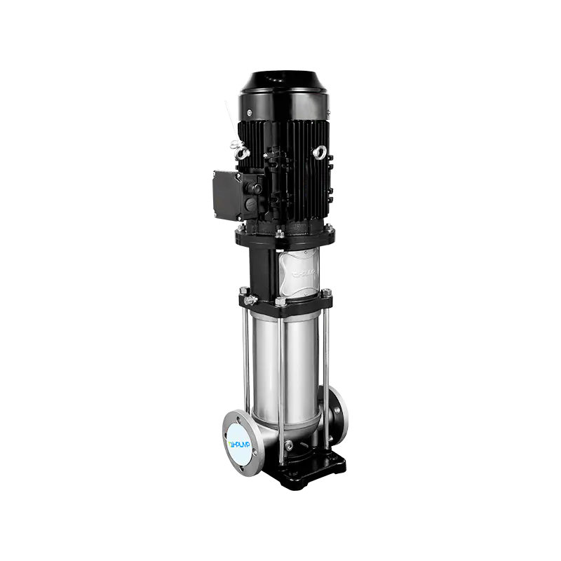
Vertical Multistage Pump (Ring Section Type)
Vertical multistage pumps stack ring-section casings vertically, with each stage formed by a casing ring bolted between flanges. This modular construction makes them easy to customize — changing the number of stages changes the pump head. The vertical orientation makes them compact, inline-installable without a baseplate, and inherently self-draining. Common formats include the CR/CRE type (Grundfos designation widely used as an industry reference) and similar variants from other manufacturers. Duty range: typically 0.5–500 m³/h, 30–600 m head. Dominant in water supply boosting, pressure washing systems, RO feed, and domestic water systems.
Primary Applications of Multistage Centrifugal Pumps
- Boiler feed water: The most demanding multistage pump application — high-pressure (typically 40–200 bar), high-temperature (feed water at 150–250°C), and continuous operation with zero tolerance for interruption. Horizontal barrel-type multistage pumps with 6–12 stages are standard for power station boiler feed. Critical design factors include NPSHA at high feed water temperature (vapor pressure is elevated, reducing available NPSH), and erosion resistance from deaerated feed water.
- Reverse osmosis (RO) high-pressure feed: RO membranes for seawater desalination operate at 55–80 bar feed pressure; brackish water RO at 8–20 bar. Multistage centrifugal pumps with stainless steel or duplex stainless wetted parts are the standard high-pressure feed pump for RO systems of all scales.
- Water supply pressure boosting: In high-rise buildings, multistage pressure booster sets maintain constant supply pressure throughout the building against the static head of the upper floors. A 20-story building requires approximately 60–80 m of additional head — a 3–4 stage vertical multistage pump provides this efficiently.
- Firefighting jockey and main pumps: Sprinkler and hydrant systems require high-pressure standby capacity. Vertical multistage pumps serve as jockey (pressure maintenance) pumps, while horizontal multistage or split-case pumps handle main firefighting demand flows.
- Mine dewatering at depth: Mines at 200–1,000 m depth require pumping systems generating 200–1,000 m of head — only multistage centrifugal pumps can efficiently achieve this in a single pump set. Submersible multistage pumps are common in intermediate dewatering chambers; surface-mounted horizontal multistage pumps handle final discharge.
- Chemical process high-pressure injection: Pipeline injection pumping, chemical reactor feed, and hydrocarbon process high-pressure transfer all use horizontal multistage pumps with appropriate materials of construction (duplex stainless, Hastelloy, or titanium for aggressive duties).
Selecting Stage Count: The Engineering Approach
Stage count is determined by the required total head divided by the head per stage at the design flow. For example: a system requiring 450 m TDH at 50 m³/h, with each stage producing 90 m at BEP, requires 5 stages. In practice, the manufacturer's stage curve is used to identify the duty point, and the number of stages is adjusted to position the operating point within 80–110% of BEP flow. Adding or removing a stage shifts the head-flow curve up or down proportionally — this flexibility is one of the significant advantages of modular multistage pump construction over single-stage designs where changes require complete impeller redesign.
Difference Between Positive Displacement Pump and Centrifugal Pump
The centrifugal pump and positive displacement (PD) pump represent the two fundamental categories of pump technology, and they differ in every important operating characteristic. Choosing the wrong category is not a matter of preference — it produces a system that either cannot meet the duty requirement or operates destructively.
Operating Principle: The Core Difference
A centrifugal pump generates pressure by continuously adding kinetic energy to the fluid through a rotating impeller. The pressure it develops depends on flow — reduce the flow by closing the discharge valve, and head increases; open the valve fully, and head decreases. The centrifugal pump is inherently variable in both head and flow — it operates at the intersection of its pump curve and the system resistance curve, and that intersection changes whenever either curve changes.
A positive displacement pump captures a fixed volume of fluid in a cavity (cylinder, gear mesh, lobe space, diaphragm chamber, or cavity) and forces it out against system pressure on each stroke or revolution. Flow is directly proportional to speed and independent of pressure — a PD pump at a fixed speed delivers the same flow whether the discharge pressure is 1 bar or 100 bar (up to mechanical limits). If the discharge valve is closed completely, pressure will rise until something mechanical fails.
Flow Characteristics
Centrifugal pumps produce continuous, smooth, non-pulsating flow — ideal for most fluid handling duties. Positive displacement pumps produce pulsating flow (except for screw pumps and some peristaltic designs), because flow is delivered in discrete volumetric increments per cycle. Pulsation requires pulsation dampeners in the pipework for sensitive processes, flow measurement accuracy, or connected instrumentation. The pulsation amplitude depends on the pump type — single-cylinder reciprocating pumps have high pulsation; five-cylinder quintuplex plunger pumps have much lower pulsation from the overlapping delivery strokes.
Viscosity: The Strongest Selection Driver
Centrifugal pump performance degrades significantly with increasing fluid viscosity. Above approximately 300–500 cSt (centistokes), a centrifugal pump's head, flow, and efficiency all decline substantially, and hydraulic corrections per the Hydraulic Institute viscosity correction charts (HI 9.6.7) are required. Above 1,000 cSt, centrifugal pumps become impractical for most duties.
Positive displacement pumps handle viscous fluids with no performance degradation — a gear pump or progressive cavity pump at 10,000 cSt performs identically (in terms of flow delivery) to the same pump at 1 cSt. For heavy fuel oil (HFO), lube oil, polymers, molasses, bitumen, and other high-viscosity fluids, PD pumps are the only viable choice.
Head-Flow Relationship and Shutoff Risk
A centrifugal pump can safely run against a closed discharge valve (shutoff) for a brief period — the flow stops but the pump merely recirculates internally with increasing temperature. Extended shutoff operation causes overheating and seal damage but is not immediately catastrophic.
A positive displacement pump must never operate against a closed discharge valve. With flow delivery fixed by geometry and no compressibility in the fluid, closing the discharge causes pressure to rise until a pipe, seal, or casing fails. Every positive displacement pump installation requires a pressure relief valve on the discharge side as a mandatory safety device.
Flow Metering and Dosing Accuracy
Because positive displacement pumps deliver a fixed volume per revolution, they are inherently metering devices. A diaphragm metering pump or peristaltic pump can dose chemicals with accuracy of ±0.5–1% at a fixed speed — no flow meter required. Centrifugal pumps cannot meter by speed control with comparable accuracy because their flow depends on the system resistance curve, which varies with temperature, pipe fouling, and other factors not under direct control.
Comprehensive Comparison Table
| Characteristic | Centrifugal Pump | Positive Displacement Pump | Which Is Better For... |
|---|---|---|---|
| Flow vs. pressure relationship | Flow decreases as pressure increases (pump curve) | Flow independent of pressure (at fixed speed) | PD for constant flow; centrifugal for variable system |
| High viscosity fluids (>500 cSt) | Performance degrades severely | No degradation; often improves efficiency | PD pump always |
| Flow pulsation | None (smooth, continuous flow) | Present (varies by type) | Centrifugal for smooth process lines |
| High flow, moderate head | Excellent efficiency at high flow | Very large and expensive at high flows | Centrifugal pump always |
| Low flow, very high pressure | Inefficient at low specific speed | Efficient; well-suited | PD pump (plunger/diaphragm) |
| Shutoff (closed valve) operation | Safe short-term; overheats if prolonged | Dangerous; overpressure causes failure | Centrifugal (more forgiving) |
| Chemical dosing / metering | Not suitable (flow varies with system) | Inherently accurate (fixed vol/rev) | PD pump always |
| Self-priming capability | Requires special design (self-priming type) | Inherently self-priming (most types) | PD pump for difficult suction conditions |
| Shear-sensitive fluids | High shear — damages shear-sensitive products | Low shear (progressive cavity, peristaltic) | PD pump for food, biotech, polymers |
| Capital cost at large scale | Low for high-flow duties | High at large scale | Centrifugal for large flow rates |
| VSD energy savings potential | Excellent — power ∝ N³ | Good — power ∝ N (less dramatic) | Centrifugal for variable duty VSD applications |
Types of Positive Displacement Pumps for Context
Understanding the PD pump category in context helps clarify the centrifugal vs. PD decision:
- Reciprocating (piston, plunger, diaphragm): Highest pressure capability (plunger pumps to 1,000+ bar for high-pressure cleaning, injection moulding, waterjet cutting); high pulsation; best for precise metering and very high pressure at low flow
- Gear pump (external and internal): Compact, simple, handles viscosities from 1 to 100,000+ cSt; widely used for lube oil, fuel oil, hydraulic fluid, and chemical transfer; moderate pressure to approximately 25 bar
- Progressive cavity (PC) pump: Single-helix rotor in a double-helix stator; excellent for viscous, abrasive, or shear-sensitive slurries; widely used in wastewater sludge, food processing, and oil-field applications; low pulsation
- Peristaltic (hose) pump: Fluid contacts only the inside of a flexible hose — complete separation from pump mechanism; ideal for aggressive chemicals, abrasive slurries, and hygienic applications; low shear; fully reversible
- Rotary lobe pump: Two or more lobed rotors counter-rotate in a close-clearance casing; gentle action suitable for food-grade, pharmaceutical, and shear-sensitive applications; can handle solids and low-to-medium viscosity with sanitary construction
Selecting the Right Centrifugal Pump Type: A Decision Framework
With the full range of centrifugal pump types and the centrifugal vs. PD distinction clear, pump selection can be approached systematically using the following questions in sequence:
- Is the fluid above 500 cSt, shear-sensitive, or requires precise metering? If yes to any — select a positive displacement pump. If no — proceed to centrifugal selection.
- What is the required head? Below 200 m — single-stage centrifugal is likely adequate. Above 200 m — multistage centrifugal required. Above 600 m — high-pressure barrel multistage or consider PD alternatives.
- Is the pump installed above the liquid level? If suction lift exceeds 6–7 m and a foot valve cannot be used — specify a self-priming centrifugal or submersible pump.
- What is the flow rate? Below 500 m³/h — end-suction or inline is appropriate. 500–10,000 m³/h — split-case. Above 10,000 m³/h with low head — axial flow pump.
- What is the installation constraint? No pump room, inline required — inline pump. Deep well or sump — vertical turbine or submersible. High-rise pressure boosting — vertical multistage.
- What are the fluid characteristics? Slurry or abrasive — recessed impeller or rubber-lined centrifugal. Sewage/wastewater — non-clog impeller (single vane or vortex). Chemical aggressive — materials selection (stainless, Hastelloy, PVDF lined). Hot liquid near boiling — NPSHA calculation critical; impeller eye velocity must be minimized.
Following this sequence eliminates the majority of selection errors before reaching the pump manufacturer's catalog. The most common selection mistake is choosing a centrifugal pump for a duty that actually requires positive displacement (high viscosity, precise metering, or very high pressure at very low flow) — or specifying a multistage pump where a self-priming single-stage would solve the actual problem of unreliable priming far more economically.
Recommended Products
It is focused on the overall solution of dry bulk material port transfer system,
research and development, manufacturing, and service

 English
-
 Factory Area 5-6, No. 1118 Xin'an Road, Nanxun Town, Huzhou City, Zhejiang Province
-
 +86-4008117388
-
 [email protected]
Copyright © Zhejiang Zehao Pump Industry Co., Ltd. All Rights Reserved. Stainless Steel Multistage Centrifugal Pumps Manufacturers

